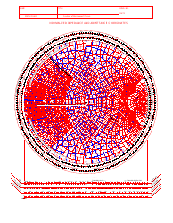
Smith Chart Engs 120 - Normalized Impedance and Admittance Coordinates

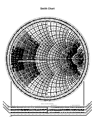
The Smith Chart is a graphical tool used in electrical engineering to help analyze and design radio frequency circuits. It specifically helps with plotting and understanding the impedance and admittance of a circuit in normalized coordinates.
The Smith Chart Engs 120 is typically filed by the educational institution or organization offering the course. The specific department or office responsible for filing may vary.
FAQ
Q: What is a Smith Chart?
A: A Smith Chart is a graphical tool used in electrical engineering to aid in the design and analysis of radio frequency circuits.
Q: What is a normalized impedance?
A: Normalized impedance is a dimensionless representation of the impedance of a circuit, which allows for easy analysis using the Smith Chart.
Q: What is a normalized admittance?
A: Normalized admittance is a dimensionless representation of the admittance of a circuit, which allows for easy analysis using the Smith Chart.
Q: What are the coordinates used in the Smith Chart?
A: The Smith Chart uses normalized impedance and normalized admittance coordinates to represent the characteristics of electrical circuits.
Q: What is the purpose of using normalized coordinates?
A: Using normalized coordinates simplifies calculations and allows for a visual representation of frequency-dependent parameters of a circuit on the Smith Chart.
Q: Why is the Smith Chart useful?
A: The Smith Chart can be used to analyze impedance matching problems, standing wave ratios, and various other circuit design and analysis tasks in RF engineering.